Ace Construction Company Texas for Beginners
Table of ContentsThe Best Strategy To Use For Ace Construction Company AustinOur Ace Construction Company StatementsNot known Facts About Ace Construction CompanyExamine This Report about Construction Company Austin
Because these products can not withstand appreciable stress, the design targets at avoiding tension in the wall. Some gravity walls do not use mortar, relying solely on their weight to remain in location, as in the case of dry stone walls. These walls usually are trapezoidal in section as revealed in Fig.2. Gravity walls need heavy structure due to the big size of the wall. They are affordable and suitable for only little heights (austin construction company). A gravity retaining wall supplied with a small quantity of reinforcement for reducing the mass of the concrete is referred to as semi-gravity keeping wall, as shown in Fig.
3. The lateral earth pressure is primarily withstood by the mass of the wall, as in the case of a gravity maintaining wall. These are the strengthened concrete walls in which lateral earth pressure is resisted by structural action of its members. The base of the wall is extended into the backfill on the heel side and is understood as heel slab, as displayed in Fig.
4. The backfill over the heel slab provides significant extra lateral stability to the wall. The back of the wall on the heel side is likewise provided a slope. This increases the width of the wall with depth, comparable to the boost in lateral earth pressure with depth. The vertical wall (referred to as stem), the heel piece, and the toe slab serve as cantilevers fixed at their junction and covering to the other end.
The Best Strategy To Use For Ace Construction Company Austin

The heel slab and the toe slab go through resultant upward soil pressure from the bottom and bend upward. Reinforcement is therefore provided on the tension side, that is, vertically on the behind of the stem and horizontally at the bottom of the heel slab and the toe piece.
Cantilever maintaining walls appropriate for keeping the backfill to moderate heights of 4-7 m. In sample, many cantilevered walls appear like "L" s or inverted "T" s. Where structure soils are bad, earth tieback keeping walls are another choice. These walls are reversed not only by a big base however also by a series of horizontal bars or strips extending out from the vertical surface area into the backfill.
As soon as an earth tieback keeping wall is backfilled, the weight and friction of the fill versus the horizontal members anchors the structure. When the height of a cantilever maintaining wall is more than about 7 m, it is affordable to supply a vertical bracing system, understood as counterforts, on the backfill side above the heel slab.
16. 5. The stem and the heel piece act as constant slabs spanning horizontally along the length of the wall in between the counterforts. The usage of counterforts decreases the flexing moment due to earth pressure visit and for this reason the size and reinforcement of the stem and the heel slab. Counterforts are subjected to tension due to the action of lateral earth pressure of the backfill on the stem.
The Facts About Austin Construction Company Revealed
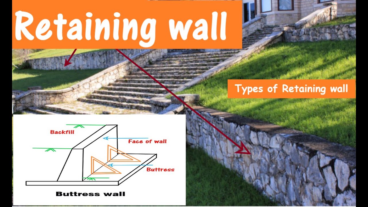
Figure 16. 6 shows a buttressed retaining wall. The structural action of the stem is the very same as in a counterfort maintaining wall. However, the heel piece functions as a cantilever piece as in a cantilever retaining wall. The toe slab acts as a continuous piece spanning along the length of the wall between you could try this out the buttresses.
ADS: Sheet stacks are versatile maintaining structures used to provide a temporary building area for building and construction of structures. Sheet piles are made of lumber, steel, or often reinforced concrete. Timber sheet stacks were utilized in the past but their reuse is limited for short-term structures up to shallow depth. For all important structures and for depth > 3 m, steel sheet stacks are more commonly used.
Enhanced cement concrete (RCC) sheet piles may be often used in great sand or soft clays. RCC stacks might get harmed or broken under driving tensions in stiff soils. Sheet stacks are installed by very first driving the steel or lumber sheets into the soil. The soil on the front side is then dug up (removed) out.

The Main Principles Of Austin Construction Company
Hence, the depth of foundation (embedment) is large compared to that in a maintaining wall. The density of sheet piles is extremely small compared with the depth and length of a wall. Hence, the weight of a sheet pile is extremely little and is usually ignored in the style. ADVERTISEMENTS: The soil on the back of the sheet pile is generally gotten rid of and backfilled with a cohesionless soil. Ace Construction Company Texas.
Nevertheless, the soil listed below the dredge level might be either a cohesionless soil or a cohesive soil, depending upon the soil profile at the website of building - Ace Construction Company Texas. Sheet piles having water on the front side utilized in dock and harbor structures to help with berthing of vessels (ships) are known as bulk heads.
Standard sections of steel sheet piles as recommended by US Steel (1984) are displayed in Table 16. 3. i. Cantilever sheet stack. ii. Anchored sheet pile. The cantilever sheet stack derives its support from the embedment into the underlying soil listed below the dredge level, as displayed in Fig. 16. 11.
In the case of anchored sheet stacks, additional lateral assistance is provided by methods of anchor rods fixed to the sheet stack near the top and anchored suitably, as shown in Fig. 16. 12. The lateral best site stability of anchored sheet piles is obtained both from the embedment into the soil below the dredge level in addition to by the support supplied by the anchor or tie rod.